Nothing to lose really.

Would this work ?

132408-93746279378.jpg


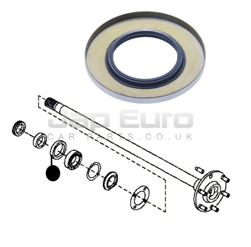
There is a spacer inside between the drum and the back plate , if you made yours like this the piece shown here with the studs could rotate inside the brake shoes ? The far wall of the drum nearest the centre of the wheel hub could be drilled to mate with this piece and screwed through from the 5 spoke side of the hub ?

Paul
Hi Paul,
No idea if that (above) would be do-able TBH, but I see what that is driving at.

I am trying to make the arrangement as transparent to "normal" as possible, so if it has too many problems/issues it can be reverted back to "Standard" with no detriment to the drum-hubs themselves.
At the moment I have a hub that I can turn and the axle turns with it (and vice-versa) but the backplate wants to turn as well because it needs to be axially aligned with the hub but not clamped tight between the inner and outer spacers. All I have to do to "free" the backplate is machine a new outer spacer, but make it with a stand-off shoulder on it. Then the backplate can be fixed to my outer axle-tube (like we normally pin it with an anti-rotation bolt/pin) and it will be stationary while the hub and inner driveshaft rotate as one. For the driving of the hub I can either put a drive pin through the axle and the walls of the hub, or I can make a cap with a drive-dog that fits between the hub's spokes. It is interesting to try and subvert the original design of the hub and its working operation without having to destroy/alter it in any major way.

Do I think it CAN be done..... yes, but I do wonder about the practical real-life operation of it.
  • Will the drive shafts flex and the wheels "wobble"?
  • Will the drive pins/dogs be adequate to transmit the torque from a laden standing start?
  • If it was easy to do, why are there not loads of detailed "how to's" all over the Velo/Web-world?

If I can't get this to work (although I think I can) I will fall back to driving the DMR hubs that came off the WD2 whose frame I sold to Emma.
Personally... I would rather use drum-hubs.

Dan.
 
OK, I made a new spacer for one of the hubs and put together a very simplistic "Proof Of Concept" model of what I am trying to achieve.
The POC model includes:
  • an outer axle-tube
  • a 12mm bolt masquerading as an axle
  • Some 12x28x8 bearings
  • A modified external spacer to allow the hub's backplate to float free.
It seems to work in principle, turning the axle (in either direction) turns the hub shell in the same direction.
I guess I will need to do more to work out how to implement a drive-dog/drive pin affair.

 
I agree that a drive dog will be better than a pin. Do you intend to have rear suspension or are you locking the axle solidly as part of the chassis?
 
I agree that a drive dog will be better than a pin. Do you intend to have rear suspension or are you locking the axle solidly as part of the chassis?
My thinking is to build this as a discrete unit onto a rigid frame with the 2WD unit in the middle. Whether the "frame" itself is on a pivot that can be suspended against the main keel is an option. No independent L-R suspension, but maybe some suspension to smooth out the bumps like I have on my Python maybe?

20210730-100454.jpg
 
A 900mm length of 32x2mm tube has arrived. :)
Let the tom-foolery begin.
Plan "A" is to determine the overall length of axle tube required, cut to that length and shove the bearings, keepers and a 12mm axle in there.
Then add the basket frame around the centre section then cut the middle out for the inner bearing sets and the 2WD unit to go in.
After that, if the thing seems sturdy enough it will be time to think on how to put it onto a delta frame. :D
 
Will this not lock you into building standard delta ? is that the plan ?
Overall frame is along the same lines, but hoping to get a bit Hase-like. :)
Track? Hmmmm...... 30...32 maybe.
What kind of wheels to you put on these?
No Idea what goes on those. Mine is going to have 20" hub-braked wheels........... IF I can get the concept to work.... of course. :D
 
Last edited:
I imported it from Dream Bike - Brazil a couple of years ago. The day it arrived my Clarke Welder (purchased in 1989) caught fire and finally ended up at our local Recycling plant!

Steve
 
I've been a bit "unwell" and not done anything on this for a while except gather some materials.

One aspect of "Driven hubs" is the requirement to secure the axle supporting bearings in position so that the axles and the "ends" cannot drift left/right.
On the PPP (perfect Python Pivots) I did this with inner & outer bearing race separator sleeves (as the distance between the bearings were small).
For this implementation I intend to machine some steel inserts that perform this function and are puddle-welded in place within the outer axle tube.
Bearings will be removable/replaceable (of course). 🙃
 
It seems that the manufacturing tolerances as applicable to standard round bar mean that a 12mm bar is not in fact 12mm and they can roll that puppy to +/- 0.07mm so as an axle it won't pass through your bearings. :eek:
I have found that at one end of a 900mm length the bearing will slip on and pass along the first inch, but no further; while at the other end bearing will not fit at all!

This is not the same for 12mm Silver steel bar (as used for layshafts in gearboxes) as this can slip through the bearings as a friction fit.

I suspect that this will mean machining the ends of the axle shafts sufficiently to allow them to slip through the inner race of the bearings so that bearings can be placed at each end of the half-shafts.
It is all do-able just more work than anticipated. :(
 
There certainly is some amount of manufacturing tolerance involved. Ideally the shaft will be held to the minus side and the bearing to the plus side but I'm sure it doesn't always come out that way. I bought .750 inch pillow block bearings and they are slightly on the plus side.
 
Have you tried precision round bar / tube. I have no idea of the tolerances but the name bodes well. There are a couple of sellers on ebay. If the bar in question is only driving rather than load bearing then tube will easily do and save weight.
 
Have you tried precision round bar / tube. I have no idea of the tolerances but the name bodes well. There are a couple of sellers on ebay. If the bar in question is only driving rather than load bearing then tube will easily do and save weight.
Hi Popshot, YES precision tube from brilliant2buy on eBay has been my "go to" for a long time now, but for this application I wanted to use bar because I intend to pin/bolt through it and I wanted the "meat" of a bar.
I tried feeding a bit of 12mm OD x 2mm wall precision tube through and it too is jamming (like Bob Marley). :)
I can see that it's only 0.07 out and although a 12mm reamer will pass through the bearings this bar won't, so the machining of both ends of each half-shaft may be required.
I will sort it...... eventually. :D
 
Last edited:
Back
Top